Raycreate’s ethos transcends geographical boundaries, embracing the rich tapestry of the Philippine market. Armed with insights gleaned from years of immersion in Manila’s 3D game asset development scene, we champion the untapped potential of local talent. Our mission is clear: to empower Philippine innovators, providing them with the tools to break free from conventional constraints in product development and prototyping, to unleash their creative genius on the world stage.
Boosting Your Vision
into Reality
Engaging with Raycreate means you will dodge many common traps of product development and prototyping; associated with the limitations of conventional prototyping methods such as CNC milling, injection molding, and other additive manufacturing technologies like FDM 3D printing. Raycreate’s laser-focused SLS service works with challenges—parsing and processing them like the friction of contact with reality, ensuring your vision emerges intact and as a beacon of industrial excellence. Let’s not just bring your ideas to life; let’s imbue them with a legacy, transforming every potential setback into a leap forward, exponentially speeding up your time-to-market.
Why Choose Raycreate?
At Raycreate, we redefine boundaries, deploying our cutting-edge S2 SLS 3D printer by Sintratec AG. With this S2 system, we can deliver unmatched precision and quality, because of its cylindrical build volume, high-resolution laser sintering capabilities, and robust material versatility. Moreover, the essence of SLS 3D printing goes far beyond just the 3D prints themselves. It is a mindset-shifting methodology for success. SLS 3D printing enables instant RFQ and QC. Thanks to our embedded Fabrex RFQ module we can offer you instant 3D model upload, costing transparency, and geometry QC. Whether your project requires a vertical slice prototype for thorough testing or a custom-tailored solution for small production runs, Raycreate stands as your trusted ally. Our collaboration with Sintratec and Fabrex enables us to help you enter into a transformative flow, shifting your development cycles and prototyping sprints into a revolutionary methodology that doesn’t just meet your goals and targets but gets you ahead of the curve sustainably.
Case Studies
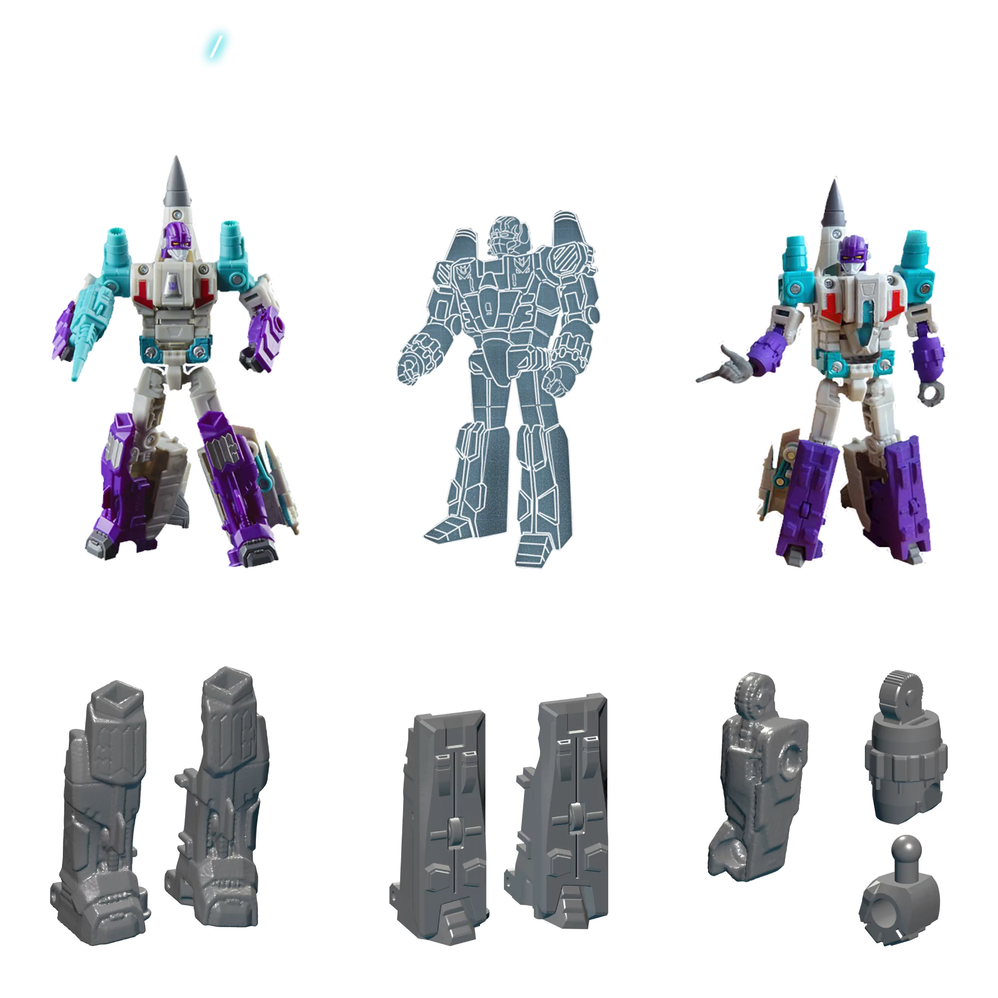
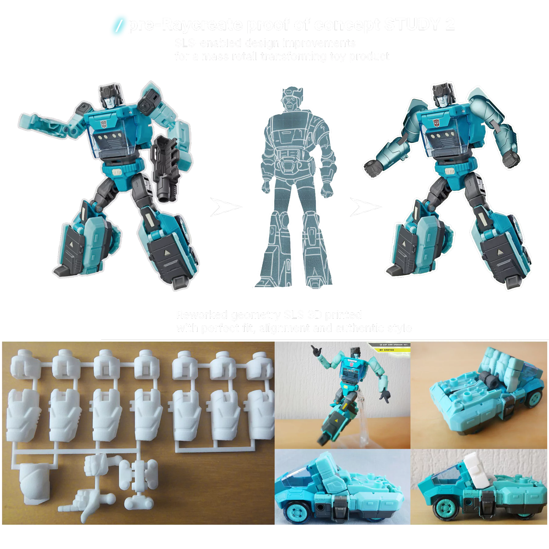
At this stage, the Case Study page presents visual examples and explanatory captions that illustrate:
SLS surface characteristics
geometric freedom
functional assemblies
batch nesting concepts
As Raycreate progresses, this page will evolve to include documented project journeys and outcomes.
Raycreate SLS Design Guidelines
Bounding Box
Max 150 x 390 x 150 mm Min 7.5 x 7.5 x 7.5 mm
The bounding box is a 3D imaginary outline of a box that encloses the smallest area occupied by your model. Your model must fit within the minimum and maximum bounding box sizes. If the size of the model is close to the maximum bounding box, then the printing orientation will be restricted.
Walls
Supported wall thickness Min 0.5 mm
Unsupported wall thickness Min 0.5 mm
A supported wall is connected at least on two sides of the wall, while an unsupported wall is connected only one side of the wall. Walls that do not meet the minimum requirements may not survive printing and cleaning processes.
Wires
Supported wall thickness Min 0.5 mm
Unsupported wall thickness Min 0.5 mm
A wire is a rectangular, circular or even triangular feature that is thinner in its unconnected directions than its length. A supported wire is connected at least on two sides of the model, while an unsupported wire is connected on one side of the model. Wires that do not meet the minimum requirements may not survive printing and cleaning processes.
Details
Embossed Details 0.2 mm high & wide for details 0.3 mm high & 0.5 mm wide for details 0.5 mm high & wide for text
Engraved Details 0.2 mm deep & wide for details 0.3 mm deep & 0.4 mm wide for details 0.5 mm deep & wide for text
A wire is a rectangular, circular or even triangular feature that is thinner in its unconnected directions than its length. A supported wire is connected at least on two sides of the model, while an unsupported wire is connected on one side of the model. Wires that do not meet the minimum requirements may not survive printing and cleaning processes.
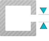
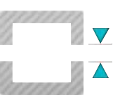
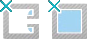
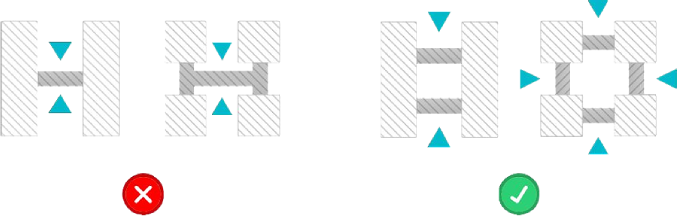
Escape Holes
Single Escape Hole Diameter 4.0 mm & 10.0 mm
Multiple Escape Hole Diameter 2.0 mm & 8.0 mm
Escape holes are necessary to empty the support material of a hollow model. Two escape holes at the opposite ends of the model is optimal for the support removal process. Please consider the size of your model and make the escape holes bigger or add more escape holes as needed as minimum guidelines will not always be adequate for large models.
A single escape hole at the end of a cavity will not allow material in the corners near the escape hole to fully escape. So we recommend multiple escape holes at both ends of the cavity.
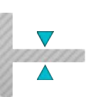
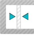
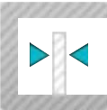
Clearance
Single Escape Hole Diameter 1.0 mm
Clearance is the space between two individual parts in a model. If the space among the individual parts do not meet the minimum clearance, then parts can fuse together or can be difficult to clean. This is important for movable pieces like hinges, gears, etc.
Sprues
2.0 mm thick, attached in at least 2 places per part. Sprues are wires that keep two or more parts together. Parts should be connected with a minimum of two sprues each.
Freedom from fear.
With our SLS service we can provide you with pathways away from this realm of fear and into a realm of enlightenment and resolve.