Raycreate — Empowering Filipino Ingenuity with Advanced Additive Manufacturing
Raycreate’s workflow is designed to reflect the realities of SLS manufacturing, while remaining accessible to product teams and SMEs.
1. Upload your 3D file
Customers begin by uploading their 3D model through the online quotation interface. The system allows them to select the applicable production settings and instantly generates a baseline quotation using Raycreate’s current material and process parameters.
2. Quote generation and submission
Instead of relying on vague or purely manual estimation, Raycreate uses a structured digital quoting workflow. Customers can review the generated quotation and submit their request directly through the system. This provides a clear starting point for project evaluation and production planning.
3. Review and order confirmation
Submitted quote requests are reviewed on the Raycreate side before production proceeds. This allows project-specific checks where needed, particularly for build planning, batch suitability, and practical manufacturing considerations. Once confirmed, the client receives the final order communication and payment instructions.
4. Production planning
Approved parts are scheduled into SLS production batches. Because Selective Laser Sintering is inherently a batch-based process, proper planning supports:
efficient use of build volume
consistent mechanical results
stable cost management
controlled turnaround expectations
5. Printing and post-processing
Parts are produced using industrial SLS technology and PA12 nylon, followed by controlled de-powdering, visual inspection, and handling appropriate to the part type and intended use.
6. Delivery and iteration
Completed parts are packed and shipped with clear order reference and traceability. Where relevant, client feedback can inform future revisions, design adjustments, or next-stage development work.
Complex Geometry, Produced with Purpose
Selective Laser Sintering enables design freedom that many other manufacturing methods cannot offer:
Mechanical accuracy with complex geometries SLS excels at producing parts with interlocking features, internal mechanisms, and functional assemblies—well beyond what FDM, SLA, or DLP typically support.
No support structures required Because parts are supported by surrounding powder, overhangs and intricate features can be printed without added supports, preserving surface integrity and design intent.
Hollow structures without infill SLS allows for hollow parts without traditional infill patterns, maintaining strength while reducing weight and material usage—an important factor for sustainable prototyping and fast iteration.
More Than Parts: A Development Methodology
SLS is not just a fabrication method—it can be used as a development strategy.
By leveraging nesting, batch production, and repeatable material behavior, SLS enables teams to restructure development workflows. For example:
demonstration of repeatability before committing to tooling
This structured approach helps teams manage pressure from tight schedules, budget limits, and external stakeholders—while maintaining technical clarity.
Expertise You Can Rely On
International experience Raycreate builds on years of SLS exposure serving European and American markets.
Structured support Our bespoke CRM ensures every project is monitored, annotated, and traceable throughout its lifecycle.
Flexible engagement Custom requests, priority handling, and tailored logistics are available for projects with specific needs.
Ready to explore what SLS can unlock for your project?
Connect with Raycreate and move from assumption to validation.
Bounding Box
Max 150 x 390 x 150 mm Min 7.5 x 7.5 x 7.5 mm
The bounding box is a 3D imaginary outline of a box that encloses the smallest area occupied by your model. Your model must fit within the minimum and maximum bounding box sizes. If the size of the model is close to the maximum bounding box, then the printing orientation will be restricted.
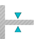
Walls
Supported wall thickness Min 0.5 mm
Unsupported wall thickness Min 0.5 mm
A supported wall is connected at least on two sides of the wall, while an unsupported wall is connected only one side of the wall. Walls that do not meet the minimum requirements may not survive printing and cleaning processes.
Wires
Supported wall thickness Min 0.5 mm
Unsupported wall thickness Min 0.5 mm
A wire is a rectangular, circular or even triangular feature that is thinner in its unconnected directions than its length. A supported wire is connected at least on two sides of the model, while an unsupported wire is connected on one side of the model. Wires that do not meet the minimum requirements may not survive printing and cleaning processes.
Details
Embossed Details 0.2 mm high & wide for details 0.3 mm high & 0.5 mm wide for details 0.5 mm high & wide for text
Engraved Details 0.2 mm deep & wide for details 0.3 mm deep & 0.4 mm wide for details 0.5 mm deep & wide for text
A wire is a rectangular, circular or even triangular feature that is thinner in its unconnected directions than its length. A supported wire is connected at least on two sides of the model, while an unsupported wire is connected on one side of the model. Wires that do not meet the minimum requirements may not survive printing and cleaning processes.
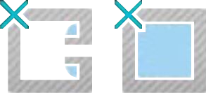
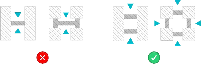
Escape Holes
Single Escape Hole Diameter 4.0 mm & 10.0 mm
Multiple Escape Hole Diameter 2.0 mm & 8.0 mm
Escape holes are necessary to empty the support material of a hollow model. Two escape holes at the opposite ends of the model is optimal for the support removal process. Please consider the size of your model and make the escape holes bigger or add more escape holes as needed as minimum guidelines will not always be adequate for large models.
A single escape hole at the end of a cavity will not allow material in the corners near the escape hole to fully escape. So we recommend multiple escape holes at both ends of the cavity.
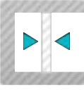
Clearance
Single Escape Hole Diameter 1.0 mm
Clearance is the space between two individual parts in a model. If the space among the individual parts do not meet the minimum clearance, then parts can fuse together or can be difficult to clean. This is important for movable pieces like hinges, gears, etc.
Sprues
2.0 mm thick, attached in at least 2 places per part. Sprues are wires that keep two or more parts together. Parts should be connected with a minimum of two sprues each.
Freedom from fear.
With our SLS service we can provide you with pathways away from this realm of fear and into a realm of enlightenment and resolve.